



.png)


.png)



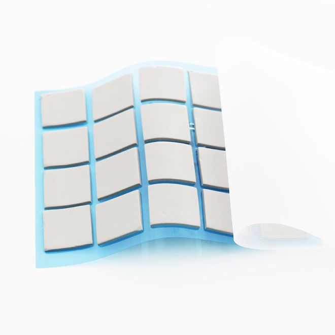
🔧 Understanding Thermal Gap Filler Pads and Their Core Functions
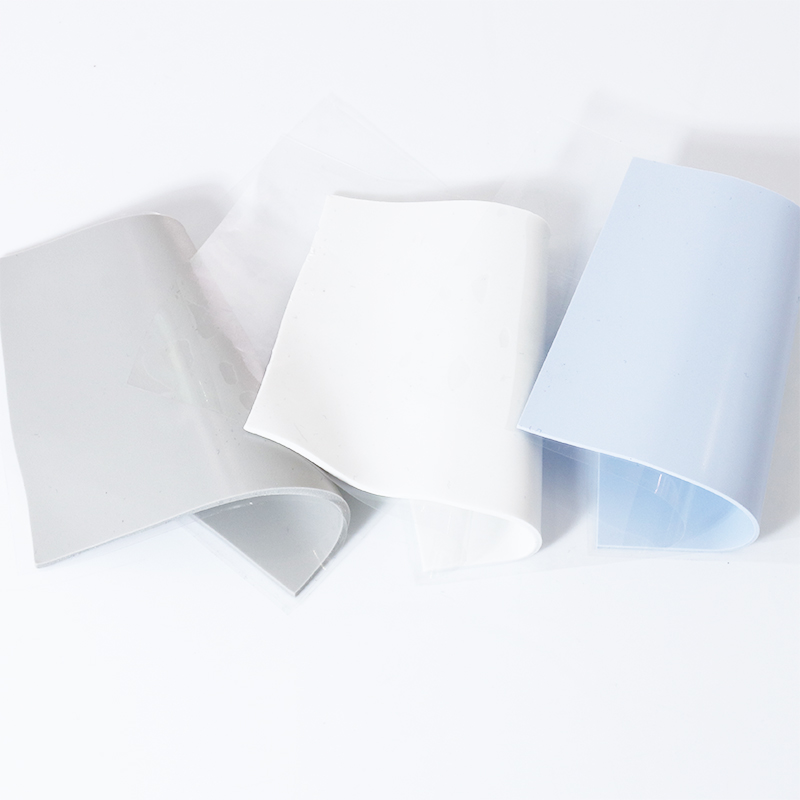
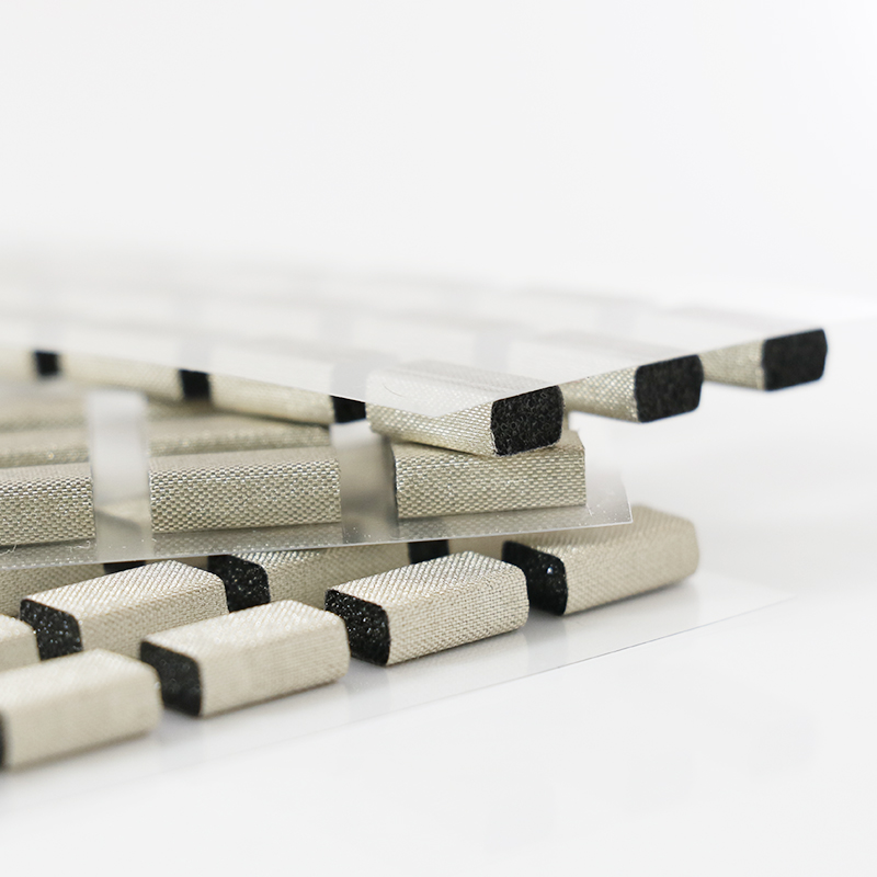
Thermal gap filler pads bridge the space between hot components and heat sinks. They reduce contact resistance, spread heat evenly, and protect devices from thermal stress and failure.
By flexing under pressure, gap filler pads fill air gaps and rough areas. This improves heat flow, supports stable performance, and extends electronic product life in harsh environments.
1. What Is a Thermal Gap Filler Pad?
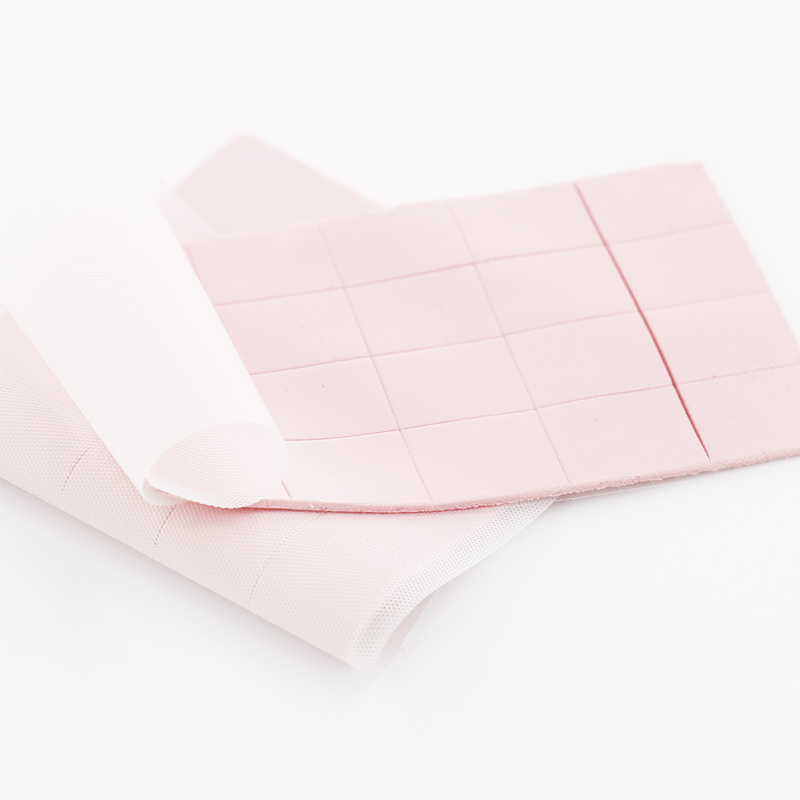
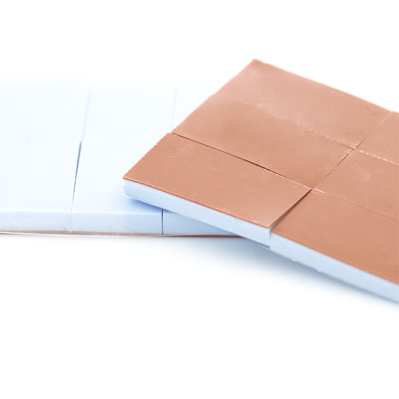
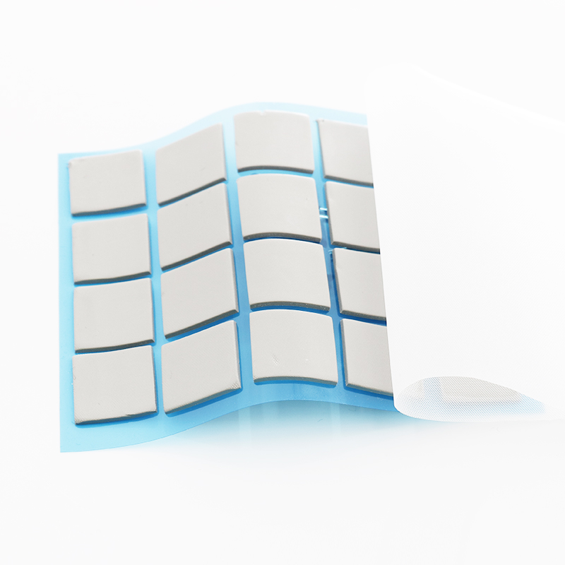
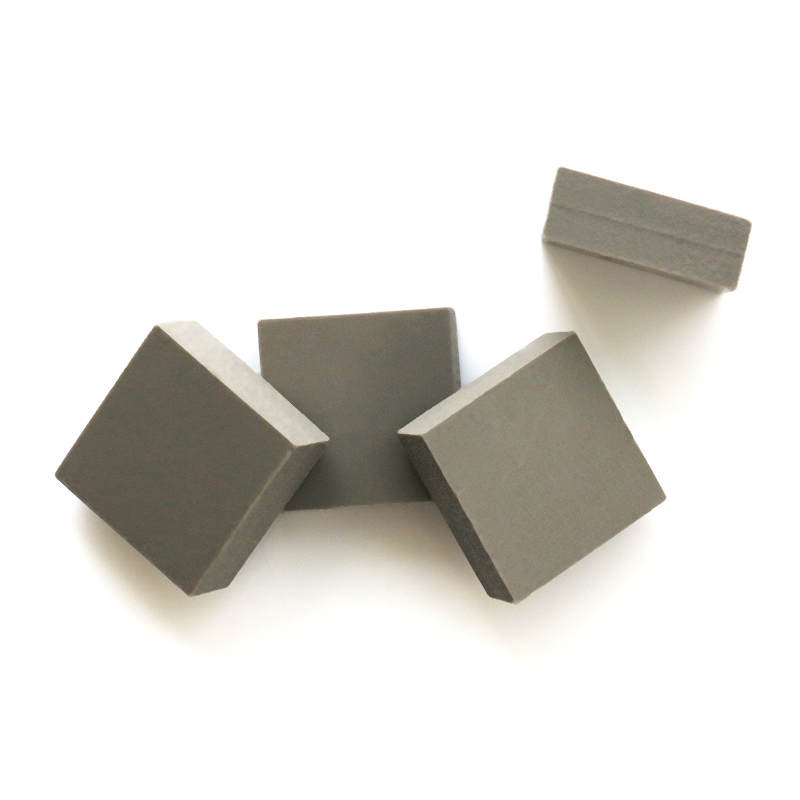
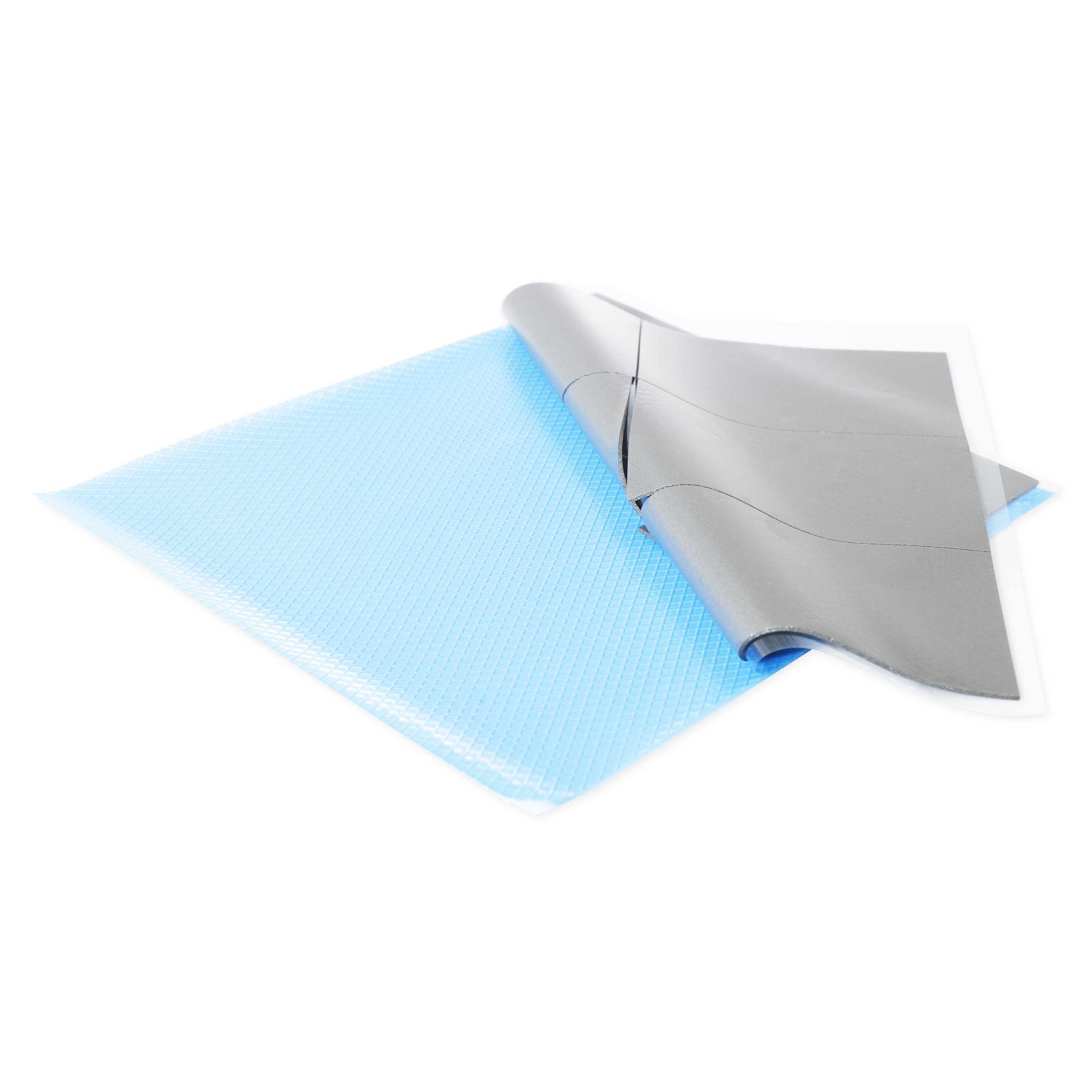
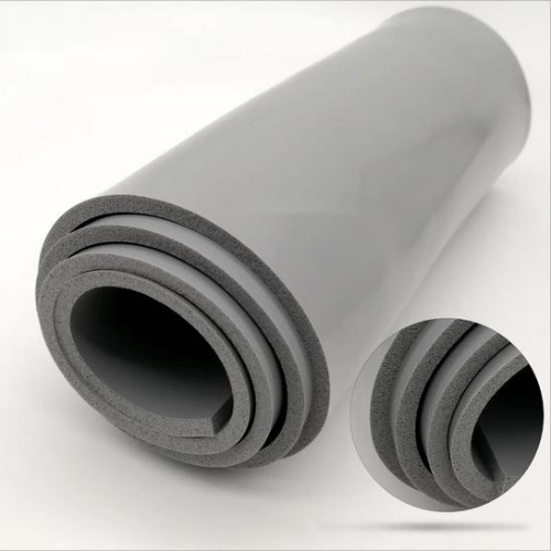
A gap filler pad is a soft, thermally conductive sheet placed between components and a cold surface to improve heat transfer and reliability.
- Replaces air gaps with conductive material
- Accommodates uneven surfaces and tolerances
- Offers electrical insulation in many formulas
2. Core Roles in Thermal Management
Gap filler pads manage heat in compact, high-power designs where direct heatsink contact is not possible.
- Lower junction temperature of chips and modules
- Reduce thermal cycling stress on solder joints
- Support higher power density safely
3. Typical Applications in Modern Electronics
Engineers use gap fillers in many sectors to stabilize device temperature and meet reliability standards.
| Application | Role of Gap Filler Pad |
|---|---|
| Power supplies | Moves heat from MOSFETs and transformers |
| EV battery packs | Balances cell temperature across modules |
| 5G base stations | Cools RF amplifiers and processors |
| LED lighting | Controls LED junction temperature |
4. When to Choose a Gap Filler vs. Grease
Use pads instead of grease when you need easy assembly, clean handling, and stable performance over many years.
- No pump-out or messy rework
- Consistent thickness and contact
- Better for automated or repeat assembly
📏 Key Factors in Selecting the Right Thickness and Hardness
The right pad thickness and hardness ensure full contact without adding excess thermal resistance. They must match mechanical gaps, pressure limits, and assembly methods.
Engineers should measure real gap ranges, stack-up tolerances, and compression forces. This avoids pad over-compression, component damage, and unreliable thermal paths.
1. Measuring Actual Gaps in Your Assembly
Start by measuring minimum and maximum gaps between components and heat spreaders to define a safe compression range for the pad.
- Use feeler gauges or 3D models
- Account for tolerance stack-up
- Consider thermal expansion during operation
2. Choosing Optimal Thickness and Compression
Pick a pad slightly thicker than the maximum gap. Aim for a controlled compression, usually around 10–40%, based on the datasheet.
| Gap Range (mm) | Recommended Pad Thickness (mm) | Target Compression |
|---|---|---|
| 0.2–0.4 | 0.5 | 20–40% |
| 0.5–0.8 | 1.0 | 20–50% |
| 1.0–1.5 | 2.0 | 25–50% |
3. Balancing Hardness with Component Stress
Softer pads conform better but may creep; harder pads support structure but can stress fragile parts like BGA or ceramic devices.
- Use low-hardness pads for small, fragile chips
- Use mid-hardness pads for power modules
- Check maximum load per component in design rules
4. Visualizing Trade-Offs with Thickness and Hardness
The chart below shows how changing pad thickness affects total thermal resistance for different hardness levels in a simplified model.
🌡️ Matching Thermal Conductivity to Your Device’s Heat Requirements
Thermal conductivity (W/m·K) defines how fast a pad can move heat. Match it to your power level, allowed temperature rise, and available contact area.
Low-power boards can use mid-range pads, while high-power modules benefit from high-conductivity materials like carbon-based fillers.
1. Estimating Required Thermal Conductivity
Use power loss, maximum allowed temperature, and interface area to estimate the needed conductivity of the gap filler pad.
- List each hot component’s power (W)
- Set target temperature limit for each device
- Check if area and pad k-value can meet that limit
2. When to Use Ultra-High Conductivity Pads
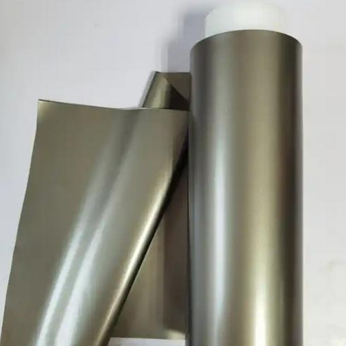
For very dense or high-power systems, consider advanced materials such as the 25W/mk Carbon Fiber Thermal Pad HRTP-M16-C250N Series to handle extreme heat loads.
| Power Density | Typical k-Value Range |
|---|---|
| Low | 1–3 W/m·K |
| Medium | 3–6 W/m·K |
| High | 6–25 W/m·K |
3. Balancing Conductivity, Cost, and Safety
Higher conductivity often costs more. Balance budget with safety margins, and consider electrical insulation needs in your selection.
- Check dielectric strength for high-voltage zones
- Evaluate long-term thermal stability in service
- Use higher k-value only where it truly adds value
🧱 How Surface Roughness and Component Layout Affect Pad Selection
Surface finish and layout strongly influence which pad you choose. Rough, uneven areas need softer, thicker materials to form reliable contact.
Crowded boards, mixed heights, and sharp edges all demand careful pad design to avoid air gaps and stress concentrations.
1. Dealing with Rough or Machined Surfaces
Rough surfaces trap air and increase thermal resistance. Softer pads flow into the roughness and restore effective contact area.
- Use low-hardness pads on rough cast housings
- Avoid very thin pads on unpolished metal
- Consider surface treatment if gaps remain high
2. Handling Mixed Component Heights
When components vary in height, one pad sheet must compress differently across areas without overloading taller parts.
| Layout Type | Recommended Pad Strategy |
|---|---|
| Small height difference (<0.3 mm) | Single pad, soft, moderate thickness |
| Large height difference | Segment pads or use stepped spacers |
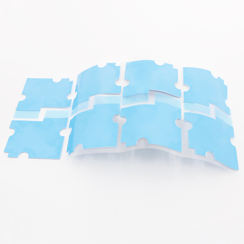
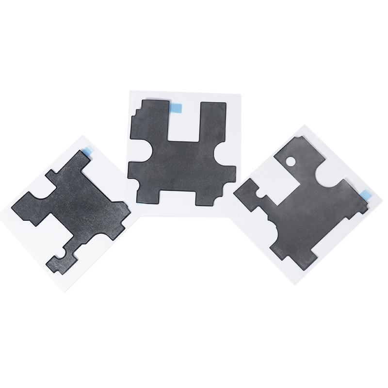
| High-density components | Precision die-cut with local reliefs |
3. Avoiding Edge Damage and Pad Tearing
Sharp corners, tall pins, or rough cutouts can tear pads during compression if the material is too brittle or hard.
- Round mechanical edges where pads contact
- Select tear-resistant, elastic formulas
- Test compression cycles in real hardware
✅ Why Choosing SpringGrass Ensures Reliable Performance and Long-Term Stability
SpringGrass offers engineered gap filler pads with stable performance, precise properties, and proven reliability for demanding thermal management projects.
By matching conductivity, hardness, insulation, and thickness, SpringGrass supports safe, repeatable designs across multiple industries and power levels.
1. Broad Product Portfolio for Different Needs
From mid-range to ultra-high conductivity, SpringGrass provides options to fit many power and safety levels.
- 5W/mk Thermal Pad HRTP-M16-T050 Series for balanced cost and performance
- 5W/mk High Dielectric Thermal Pad HRTP-M16-T050NH Series where insulation is critical
- 25 W/m·K carbon fiber pads for extreme hot spots
2. Consistent Quality and Material Stability
SpringGrass pads maintain performance across temperature cycles, aging, and compression, reducing the risk of thermal drift or early failure.
| Property | Benefit |
|---|---|
| Stable hardness | Predictable compression and contact |
| Low outgassing | Cleaner optical and electronic surfaces |
| Controlled thermal aging | Longer lifetime in the field |
3. Engineering Support for Optimized Designs
SpringGrass supports engineers with data, samples, and selection help so you can choose the right pad faster and with more confidence.
- Support for stack-up and gap analysis
- Guidance on thickness, hardness, and k-value
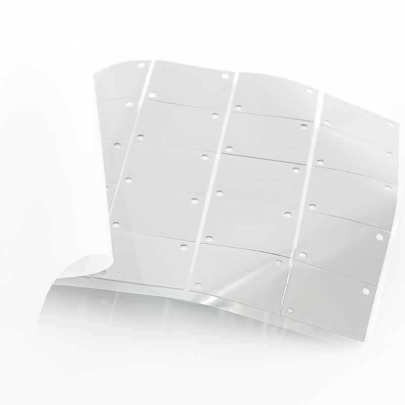
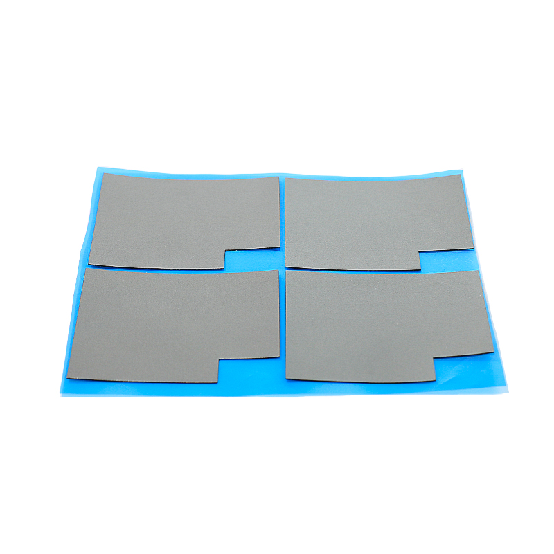
- Custom die-cut shapes for complex layouts
Conclusion
Selecting the right gap filler pad means balancing thickness, hardness, conductivity, and surface conditions. When these factors align, devices run cooler and last longer.
By using SpringGrass thermal pads and real application data, you can design reliable, safe, and cost-effective thermal solutions for modern electronics.
Frequently Asked Questions about gap filler pad
1. What does a thermal gap filler pad actually do?
A thermal gap filler pad replaces air between a hot component and a cooler surface. It improves heat flow, reduces temperature, and helps protect the device from damage.
2. How do I choose the right thickness?
Measure the minimum and maximum gap, then select a pad slightly thicker than the maximum gap. Aim for the compression range recommended in the pad’s datasheet.
3. When should I use an electrically insulating pad?
Use an insulating pad whenever high voltage, sensitive signals, or safety spacing exist between the component and heatsink or chassis. This prevents short circuits and arcing.
4. Are higher thermal conductivity pads always better?
No. Higher conductivity helps in high-power areas but often costs more. Match conductivity to power level, area, and allowed temperature, rather than choosing the highest value.
5. Can I reuse gap filler pads after disassembly?
It is not recommended. Compression, tearing, or contamination can reduce performance. For reliable thermal contact and safety, use a new pad after each major service.





 Privacy settings