



.png)


.png)



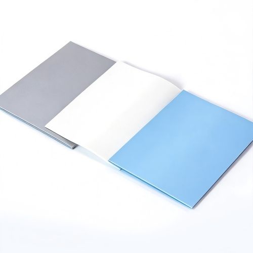
Your 2026 gadgets run so hot they could fry an egg, and every spec sheet screams “thermal management” while you stare at ten nearly identical silicone pads wondering which one won’t turn your PCB into a tiny space heater.
To fix this, match pad thickness and hardness to component gaps, then follow tested thermal conductivity data and reliability benchmarks from industry research like this authoritative electronics thermal report so your designs stay cool, stable, and future‑proof.
🔧 Key Criteria for Choosing Thermal Pad Silicone in 2026 Designs
Thermal pad silicone selection in 2026 focuses on safe heat control, tight spaces, and automated assembly. Good choices protect chips, cut rework, and support higher power density.
Engineers should compare conductivity, softness, electrical safety, and price. Clear targets early in design help avoid overheating, warping, and long debug cycles.
1. Thermal Conductivity and Power Density
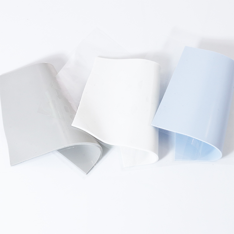
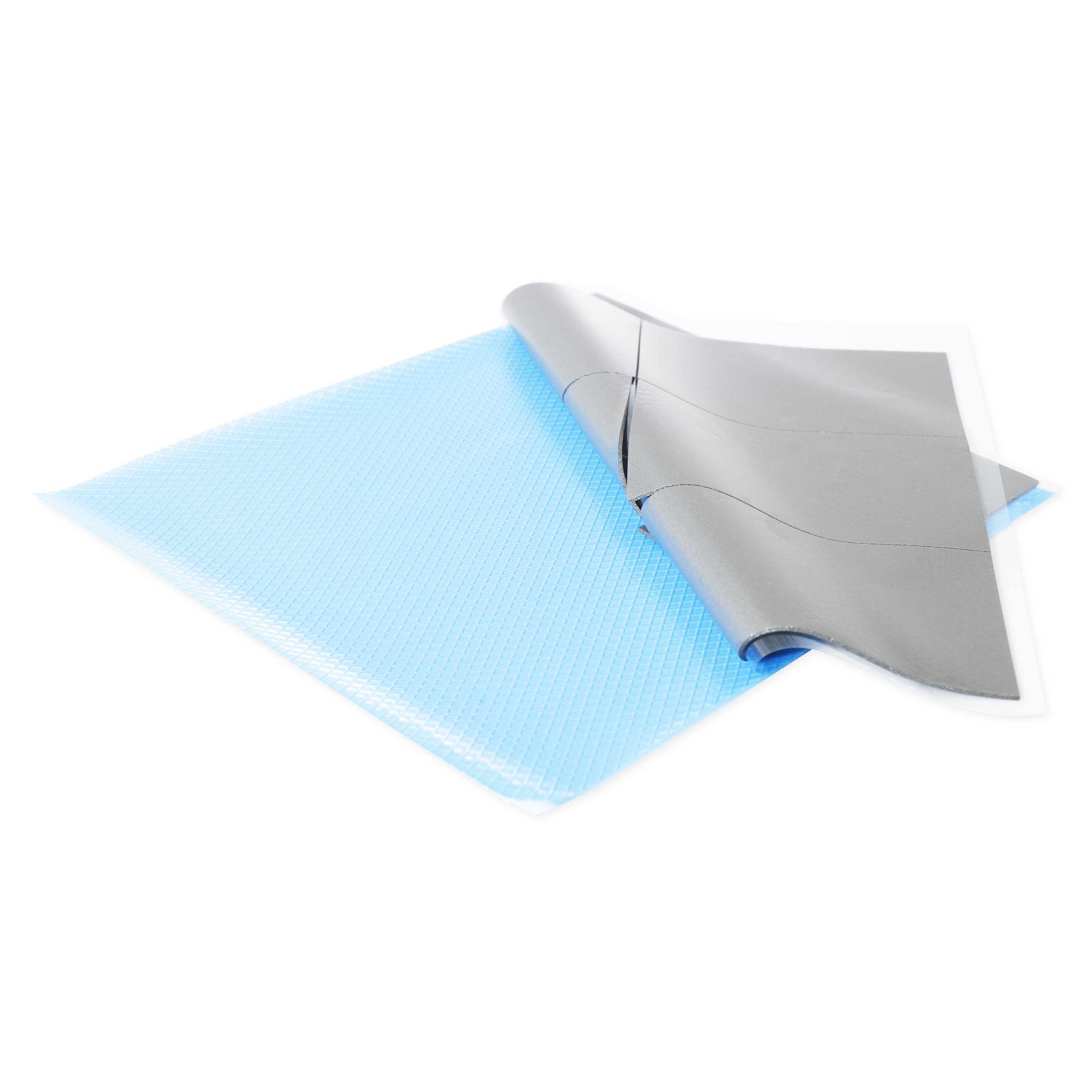
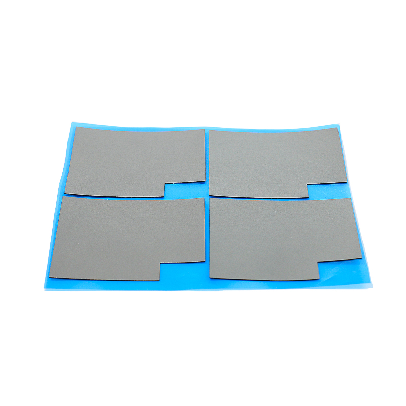
Match W/m·K level to real heat load and interface area. For mid‑power modules, consider the 6W/mk Thermal Pad HRTP-M16-T060 Series as a balanced starting point.
- Low power IoT: 3–6 W/m·K
- Mid power CPU, GPU: 6–10 W/m·K
- High power inverters, base stations: 10–12+ W/m·K
2. Electrical Insulation and Safety
Most 2026 electronics need pads that insulate while conducting heat. Check dielectric strength and volume resistivity, especially in EV, telecom, and medical designs.
- High breakdown voltage for high‑voltage boards
- Consistent insulation over temperature and time
- Clean surfaces for stable creepage distance
3. Surface Conformability and Assembly Ease
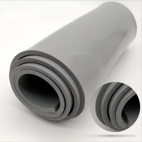
Soft, compliant silicone fills gaps between warped PCBs and rough heatsinks. This reduces thermal resistance and makes automated assembly more stable.
| Hardness (Shore 00) | Use Case |
|---|---|
| 40–50 | Fragile chips, thin PCBs |
| 50–65 | General control boards |
| 65–80 | Heavy modules, firm clamping |
4. Cost, Supply, and Global Compliance
For 2026 mass production, secure long‑term supply, stable pricing, and compliance with RoHS, REACH, and halogen‑free requirements.
- Confirm multi‑site manufacturing and safety stock
- Request CoA and reliability data
- Check recyclability and green regulations
🌡️ Balancing Thermal Conductivity, Thickness, and Compression Performance
Thermal performance depends on more than W/m·K. Pad thickness, compression, and contact pressure work together to define real junction temperatures in operation.
Use realistic stack‑ups, clamping forces, and power cycles to validate pad choices before locking the 2026 BOM.
1. Comparing 6, 10, and 12 W/m·K Pads
As power density rises, higher‑grade pads reduce temperature but cost more. Compare options like 6, 10, and 12 W/m·K against real test data, not only datasheets.
2. Setting Optimal Thickness
Thicker pads fill larger gaps but raise thermal resistance. Minimize thickness while still covering all tolerances and mechanical movement.
| Gap Size | Pad Thickness |
|---|---|
| 0.2–0.5 mm | 0.3–0.5 mm |
| 0.5–1.0 mm | 0.5–1.0 mm |
| 1.0–2.0 mm | 1.0–2.0 mm |
3. Compression and Contact Pressure
Most silicone pads work best at 20–40% compression. This ensures low interface resistance without damaging BGA solder joints or bending PCBs.
- Use torque specs for screws or clamps
- Simulate stress on tall components
- Verify no pad “pump‑out” during vibration
4. Application‑Specific Choices
For ultra‑hot zones, higher grades like the 10W/mk Thermal Pad HRTP-M16-T100 Series and 12W/mk Thermal Pad HRTP-M16-T120 Series help keep peak temperatures within safe margins.
📐 Matching Pad Hardness and Thickness to PCB and Heatsink Tolerances
Torque, flatness, and CTE mismatch all affect pad behavior. Right hardness and thickness protect both thermal targets and mechanical reliability.
Model worst‑case stack‑ups early so you do not over‑stress connectors, solder joints, or plastic housings.
1. Protecting Thin and Flexible PCBs
Use softer pads and lower clamp force around thin boards and flex tails to avoid bending or trace cracking during assembly and thermal cycling.
- Shore 00: 40-80 for flex areas
- Limit screw torque near connectors
- Test with thermal shock and vibration
2. Handling Large, Heavy Heatsinks
For big aluminum blocks, moderate hardness prevents pad over‑flow while keeping strong contact across the full interface area.
| Heatsink Size | Suggested Pad Hardness |
|---|---|
| Small, local | Softer, better gap fill |
| Medium | Medium hardness |
| Large, heavy | Higher hardness, stable |
3. Tolerance Stack‑Up Planning
Map total gap range including PCB warp and housing variation. Choose the thinnest pad that still covers maximum tolerance and maintains compression.
🧪 Reliability Factors: Aging, Outgassing, and Long-Term Stability Considerations
2026 designs must last years in harsh climates. Thermal pads must stay stable under heat, humidity, and continuous power cycling.
Check long‑term test data and qualification reports, not just initial thermal values at room temperature.
1. Thermal Aging and Hardening
High temperatures can slowly harden some pads, raising contact resistance. Review data from 1,000+ hour aging and re‑measure thermal performance.
- Track Shore hardness drift
- Monitor thickness change
- Re‑test interface resistance
2. Outgassing and Cleanliness
Low‑outgassing silicone is key around optics, sensors, and sealed housings. Volatile siloxanes can fog lenses or affect conformal coatings.
| Parameter | Impact |
|---|---|
| VOC level | Sensor drift, fogging |
| Siloxane content | Risk for optical systems |
3. Environmental and Mechanical Cycling
Use pads tested for thermal shock, humidity, and vibration. This prevents cracking, pump‑out, and loss of contact during the product lifetime.
🏷️ When Selecting a Thermal Pad Brand, Choose SpringGrass for Consistency
Brand consistency matters as power levels rise. SpringGrass focuses on stable performance, repeatable production, and clear technical support.
This helps engineering teams shorten validation time and maintain global quality across 2026 product platforms.
1. Stable Material Formulation
SpringGrass keeps tight process control, so each batch behaves the same in compression, thermal performance, and dielectric strength across regions.
- Batch‑to‑batch traceability
- Controlled filler loading
- Documented test methods
2. Complete Performance Portfolio
With 6 to 12 W/m·K options, SpringGrass supports low‑power IoT, automotive inverters, and telecom base stations using one aligned material system.
3. Engineering and Sampling Support
Design teams can access datasheets, samples, and advice on gap, hardness, and thickness, reducing prototype loops and launch risk.
Conclusion
Choosing the right thermal pad silicone for 2026 projects means balancing conductivity, thickness, hardness, and long‑term stability. Test under real power and mechanical conditions, not just in theory.
By using data‑driven comparisons and consistent brands such as SpringGrass, engineers can control temperatures, protect PCBs, and support faster, safer electronics launches.
Frequently Asked Questions about thermal pad silicone
1. How do I choose the correct thermal conductivity?
Start from power density and target junction temperature. For moderate heat, 6–10 W/m·K is often enough. Use higher values when space is tight or power is extreme.
2. How thick should my thermal pad be?
Measure real gaps, add tolerance and warp, then pick the thinnest pad that still covers the maximum gap at 20–40% compression.
3. Can thermal pads replace thermal grease?
Often yes. Pads are cleaner and easier to assemble. For most electronics, modern high‑W/m·K pads provide similar or better stability than grease over time.
4. Do thermal pads conduct electricity?
Most silicone thermal pads are designed to be electrically insulating while conducting heat. Always confirm dielectric strength and resistivity in the datasheet.
5. How do I verify long‑term reliability?
Request aging, humidity, and thermal shock data from the supplier. Run your own tests on real assemblies to confirm pad behavior and temperature margins.





 Privacy settings