



.png)


.png)




Your laptop sounds like a jet, your console fries eggs, and you’re wondering if “hot electronics” is a feature or a fire hazard—welcome to the confusing world of thermal pads and mystery overheating.
This 2026 buyer guide shows you how to pick safe, effective thermal pads, backed by research like the NREL thermal interface materials report, so your electronics stay cool, quiet, and drama-free.
🔧 What Is a Thermal Pad and Why It Matters in 2026
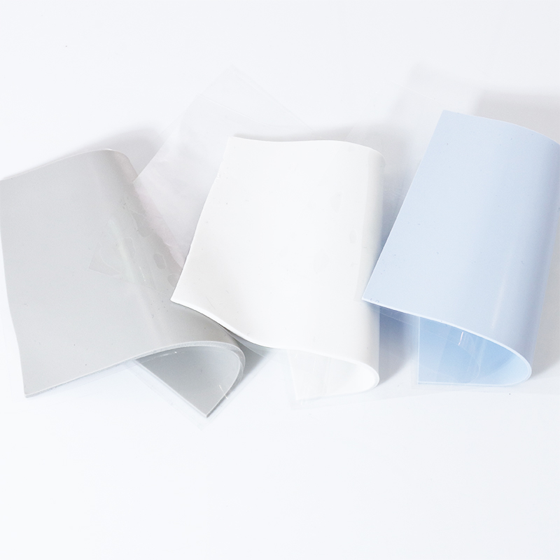
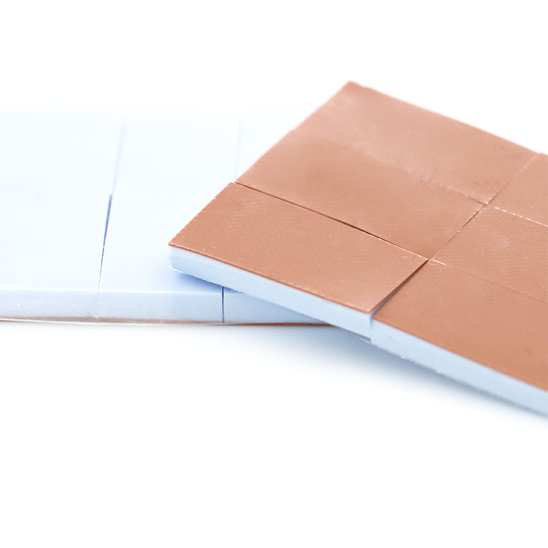
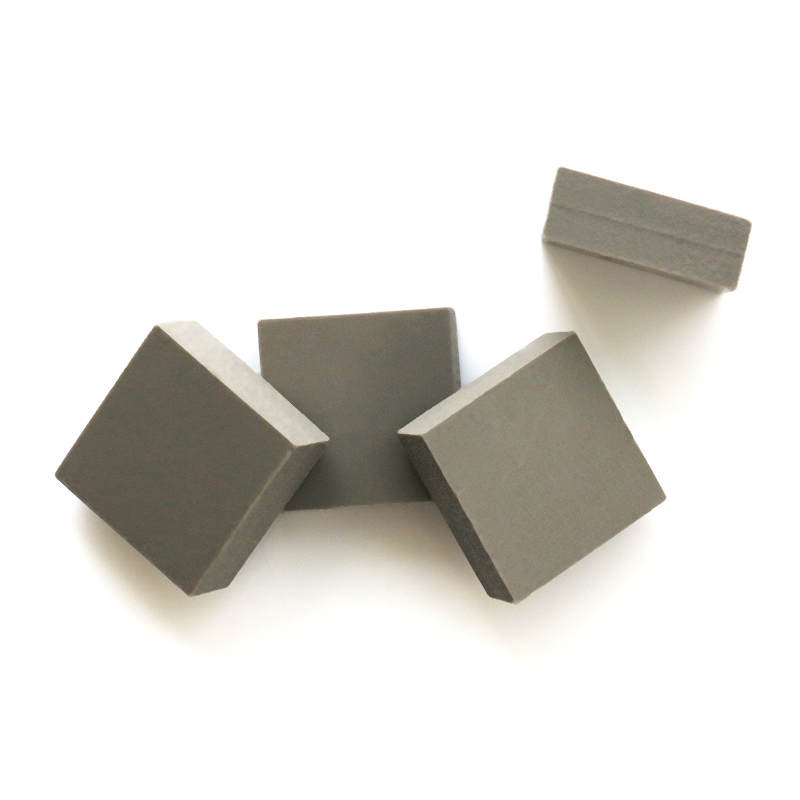
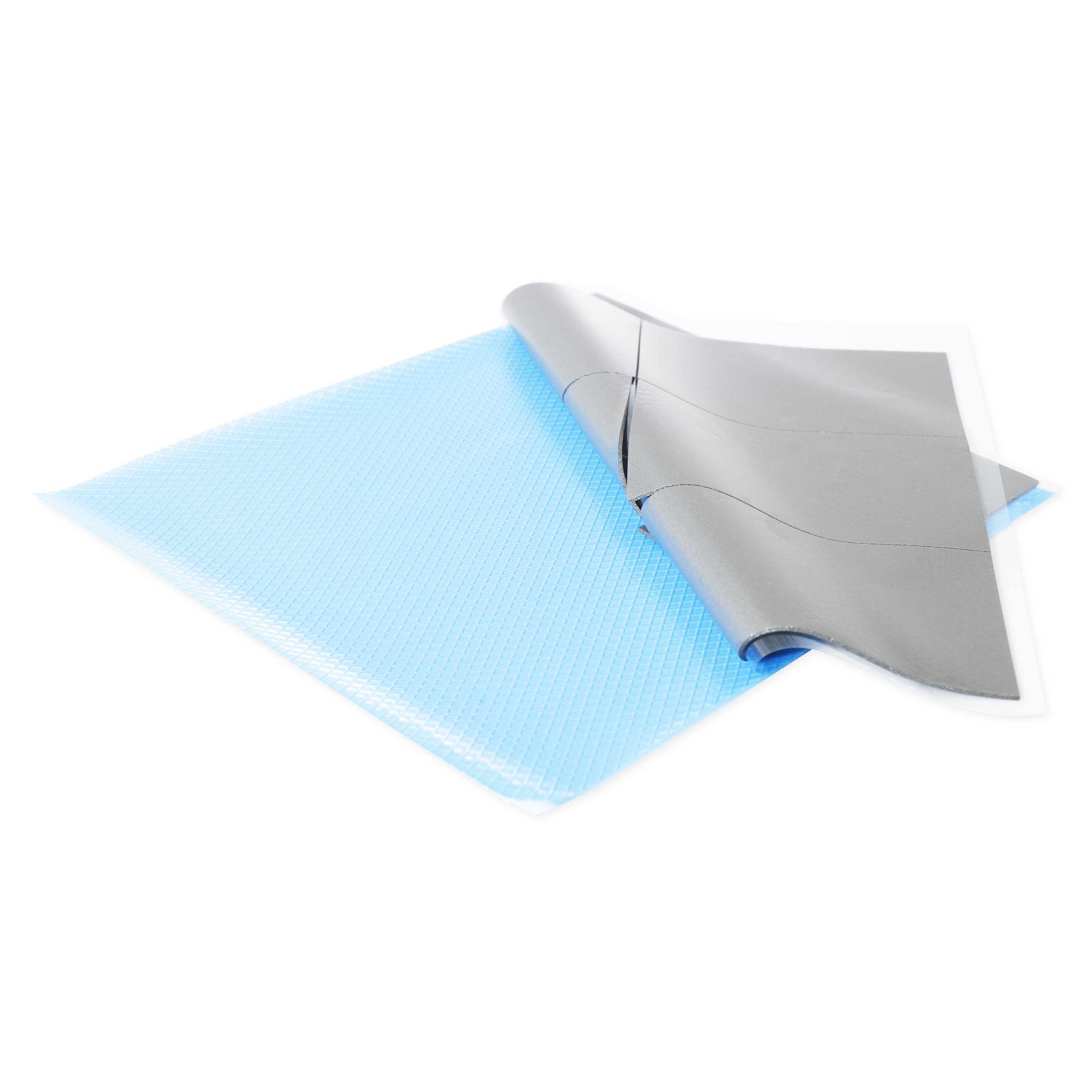
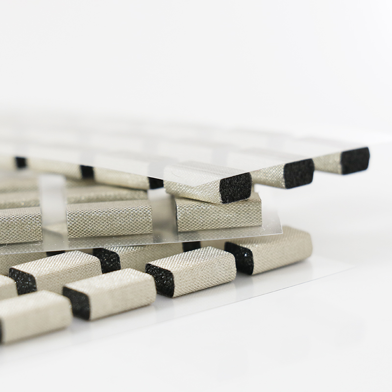
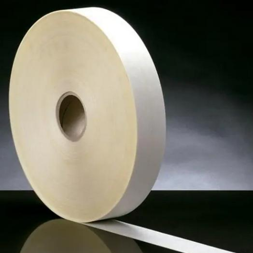
Thermal pads fill air gaps between heat sources and heat sinks. In 2026, they are critical for stable, cool operation in compact, high‑power electronics.
They improve contact, lower temperatures, and extend the life of EV chargers, 5G hardware, gaming PCs, LED drivers, and industrial control boards.
1. Role in Modern Electronics Cooling
Thermal pads sit between chips and heat spreaders to move heat safely away.
- Protect processors and power modules
- Reduce hotspot risk
- Support fan and passive cooling systems
2. Benefits vs. Thermal Grease
Pads are cleaner and easier to apply than grease, with more consistent thickness and fewer assembly errors.
| Feature | Thermal Pad | Thermal Grease |
|---|---|---|
| Cleanliness | Very clean | Can smear |
| Rework | Simple | Time‑consuming |
3. Typical Use Cases in 2026 Designs
Designers use pads across consumer, industrial, and automotive electronics.
- GPU and CPU modules
- Power inverters and DC‑DC converters
- LED lighting boards and telecom cards
4. When You Must Use a Thermal Pad
Use a pad whenever you see an uneven gap or need electrical insulation with stable thermal performance.
- Large tolerances between components
- Vibration or shock environments
- Need for clean, fast assembly lines
🌡️ Key Thermal Pad Specifications: Thickness, Conductivity, and Operating Temperature
Thermal pad specifications define real cooling performance. Focus on thickness, thermal conductivity, hardness, and operating temperature before locking your 2026 design.
Balanced choices reduce cost while keeping chips well within safe temperature limits.
1. Understanding Thermal Conductivity (W/m·K)
Higher W/m·K moves more heat, but may not always be necessary. Match pad grade to your power density and cost target.
| Series | Conductivity (W/m·K) |
|---|---|
| 2.5W/mk Thermal Pad HRTP-M16-T02550NN Series | 2.5 |
| 4W/mk Thermal Pad HRTP-M16-T040 Series | 4.0 |
| 5W/mk Thermal Pad HRTP-M16-T050 Series | 5.0 |
2. Picking the Right Thickness
Measure your gap. Choose the thinnest pad that reliably fills it after compression to keep thermal resistance low.
- 0.3–0.5 mm for tight, flat interfaces
- 1.0–2.0 mm for common power boards
- Above 2.0 mm for large tolerances
3. Operating Temperature and Reliability
Check continuous and peak temperature ratings to avoid softening, outgassing, or long‑term creep in harsh 2026 environments.
- Consumer: typically to 105–120°C
- Industrial: 125–150°C
- Automotive: often 150°C and above
4. Compression, Hardness, and Assembly
Softer pads fill uneven gaps better and reduce mechanical stress on components and solder joints.
| Property | Impact |
|---|---|
| Hardness | Controls pressure on chips |
| Compression set | Affects long‑term gap stability |
| Tackiness | Helps placement during assembly |
📏 How to Choose the Right Size and Shape for Components
Correct pad size and shape avoid edge shorting, stress, and poor heat flow, especially in dense 2026 layouts.
Plan pad geometry early in PCB and enclosure design to prevent rework later.
1. Measuring Component Footprints Accurately
Use datasheets and 3D models to define pad coverage slightly smaller than the component outline.
- Stay 0.5–1.0 mm inside edges
- Avoid covering labels or test pads
2. Managing Multiple Heights and Gaps
When components have different heights, consider stacked pads or local recesses in the heat sink.
| Scenario | Solution |
|---|---|
| Small gap difference | Use one soft pad |
| Large gap steps | Machine step or use mixed thickness |
3. Custom Shapes vs. Standard Sheets
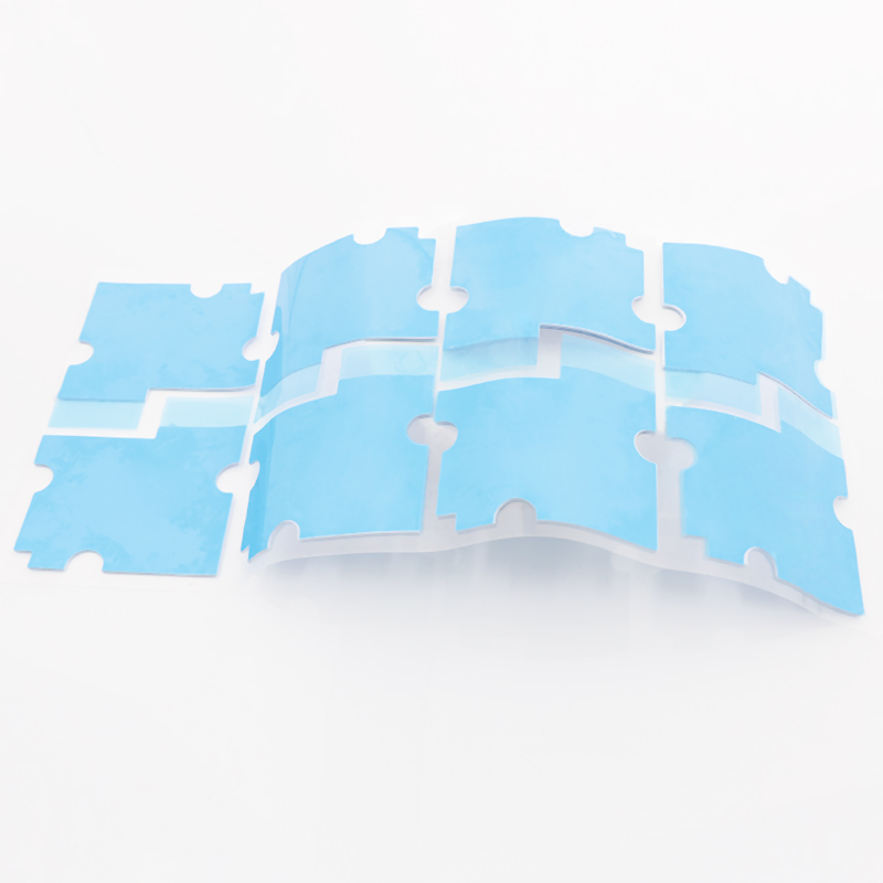
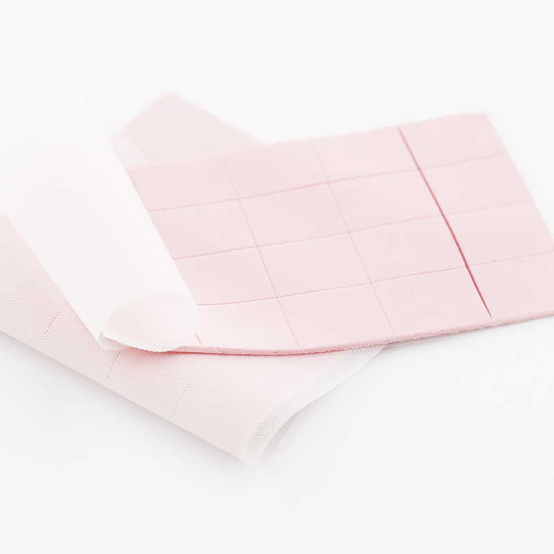
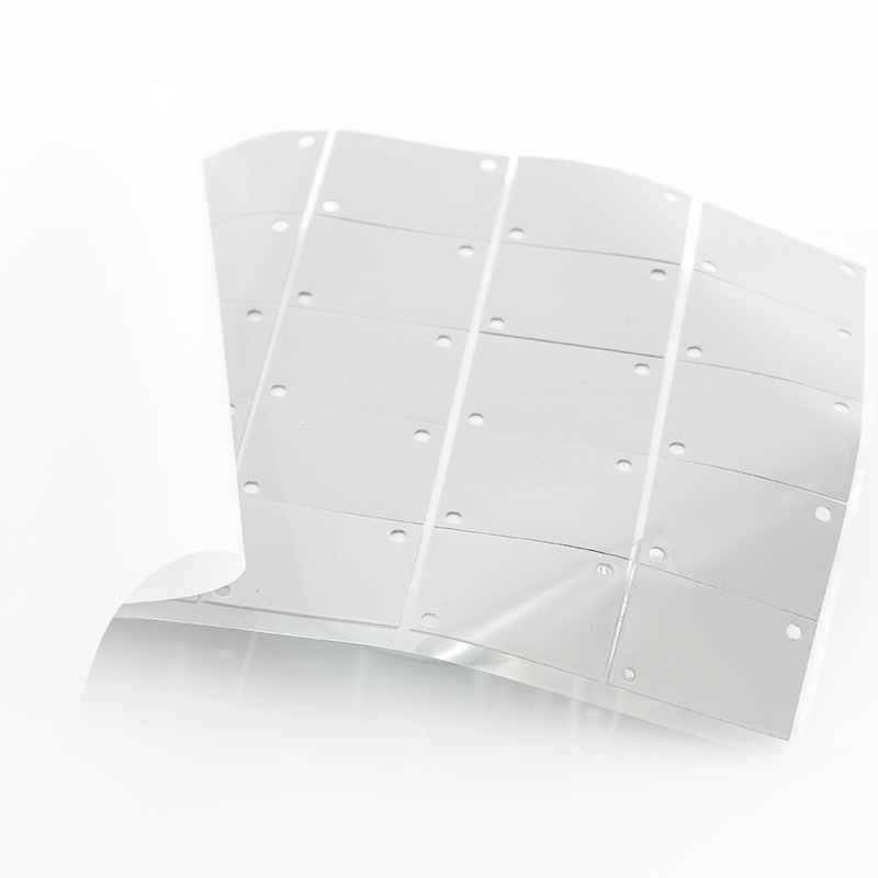
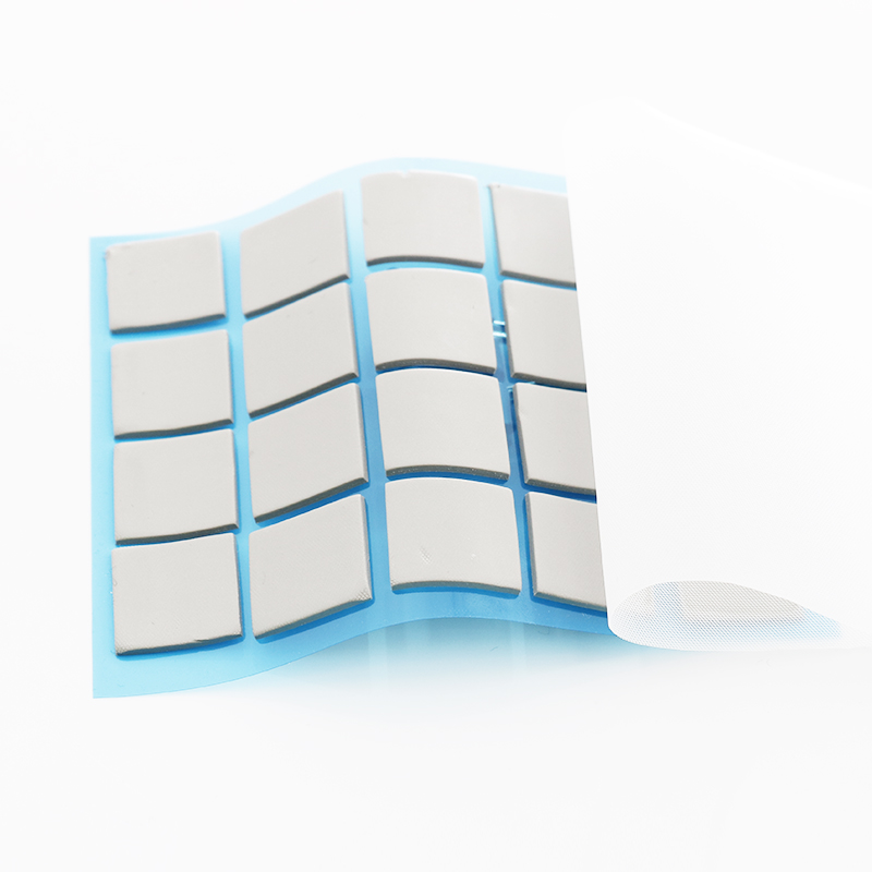
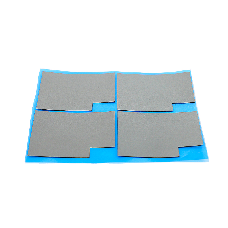
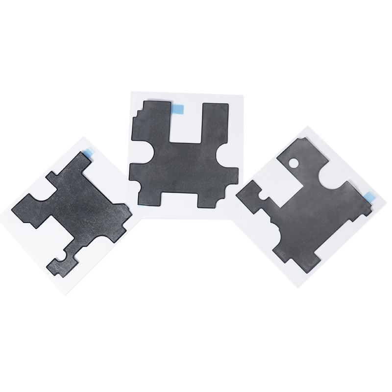
For prototypes, cut standard sheets. For mass production, use die‑cut pads to save time and reduce scrap.
- Prototype: hand cut, fast and flexible
- Mass production: pre‑cut, exact and clean
🧪 Material Types Compared: Silicone, Graphite, Ceramic, and Hybrid Pads
Material choice sets thermal performance, electrical behavior, and cost for your 2026 thermal solution.
Review pros and cons before standardizing in your platform design.
1. Silicone Pads
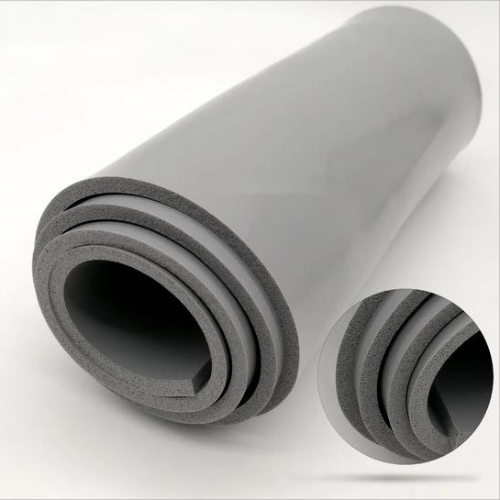
Silicone pads are the most common. They are soft, easy to use, and provide good electrical insulation.
| Advantage | Note |
|---|---|
| Good conformability | Great for uneven gaps |
| Stable over time | Low aging risk |
2. Graphite and Ceramic Options
Graphite offers high in‑plane conductivity, while ceramic‑filled pads focus on insulation and safety.
- Graphite: very high thermal, often not insulating
- Ceramic: strong insulation, robust at high temperature
3. Hybrid and Advanced Pads
Hybrid pads blend silicone with advanced fillers to balance softness, high thermal performance, and electrical safety.
- Higher W/m·K with good softness
- Better fit for compact power modules
✅ Practical Selection Checklist and Why Engineers Prefer SpringGrass Thermal Pads
A simple checklist helps you pick the right pad quickly for any 2026 design stage.
Engineers often choose SpringGrass pads for consistent quality and strong thermal performance.
1. Fast Selection Checklist
Run through this list before ordering samples or releasing a BOM.
- Power and target junction temperature
- Gap size and flatness
- Required insulation voltage
- Operating temperature range
- Assembly method and rework needs
2. Matching Series to Application
Use lower conductivity pads for mild loads and higher grades for hot spots or compact modules.
| Application | Suggested Conductivity |
|---|---|
| Low‑power control boards | ~2.5 W/m·K |
| Mid‑power telecom or LED | ~4 W/m·K |
| High‑power inverters, GPUs | ~5 W/m·K |
3. Why SpringGrass Thermal Pads Stand Out
SpringGrass pads provide tight process control, stable thermal data, and flexible customization for volume builds.
- Reliable datasheet‑to‑field performance
- Wide range of thickness and hardness options
- Support for custom die‑cut shapes and quick sampling
Conclusion
Choosing the right thermal pad in 2026 means balancing conductivity, thickness, and material against real device needs. Careful selection improves reliability, supports compact layouts, and simplifies assembly.
By focusing on gap size, power level, and safety, and by using proven series like those from SpringGrass, you can keep electronics cooler, safer, and longer‑lasting.
Frequently Asked Questions about thermal pad for electronics
1. Do thermal pads really make a big difference?
Yes. A well‑matched thermal pad can drop junction temperatures by several degrees, often enough to prevent throttling and extend component life.
2. How long do thermal pads last in real products?
Quality pads usually last the life of the device. Check for long‑term aging, compression set, and temperature ratings in the datasheet.
3. Can I stack thermal pads to fill a large gap?
You can, but it increases thermal resistance. It is usually better to choose a single thicker, softer pad designed for that gap.
4. Are thermal pads electrically insulating?
Most silicone‑based pads are insulating, but graphite pads often are not. Always confirm dielectric strength before placing near live traces.
5. When should I choose a higher W/m·K pad?
Choose a higher W/m·K pad when power density is high, airflow is weak, or you must keep junction temperatures well below maximum ratings.





 Privacy settings