




.png)


.png)



Your gadgets keep buzzing, your circuits keep failing, and every time you say “ESD,” someone thinks it’s a new boy band—static chaos clearly owns your workbench.
To fight the zap, use conductive foam: it tames ESD, protects components, and follows standards like ESDA ESD protection guidelines.
⚡ Structure and Composition of Conductive Foam Materials
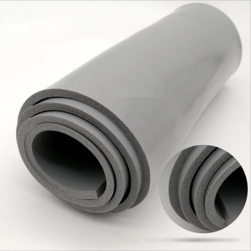
Conductive foam combines soft polymer cells with conductive paths. Engineers use it to block EMI, cushion components, and maintain stable electrical contact in tight spaces.
Its structure depends on foam type, filler choice, and surface treatment. These factors directly affect shielding level, resistance, and long‑term reliability.
1. Base Foam Types and Cell Structure
Most EMI foams use polyurethane or polyethylene. Open or closed cells decide airflow, resilience, and contact behavior at different compression levels.
- Open‑cell: better compression range, stable contact
- Closed‑cell: lower water uptake, higher stiffness
- Fine cells: smoother force curve
2. Conductive Fillers and Coatings
Metal particles, carbon, or plated surfaces build the conduction network. Designers balance cost, weight, and shielding level for each project.
| Filler Type | Main Benefit |
|---|---|
| Silver / copper | High conductivity, wide frequency range |
| Nickel | Cost control, good corrosion resistance |
| Carbon | Lightweight, anti‑static use |
3. Core Product Forms
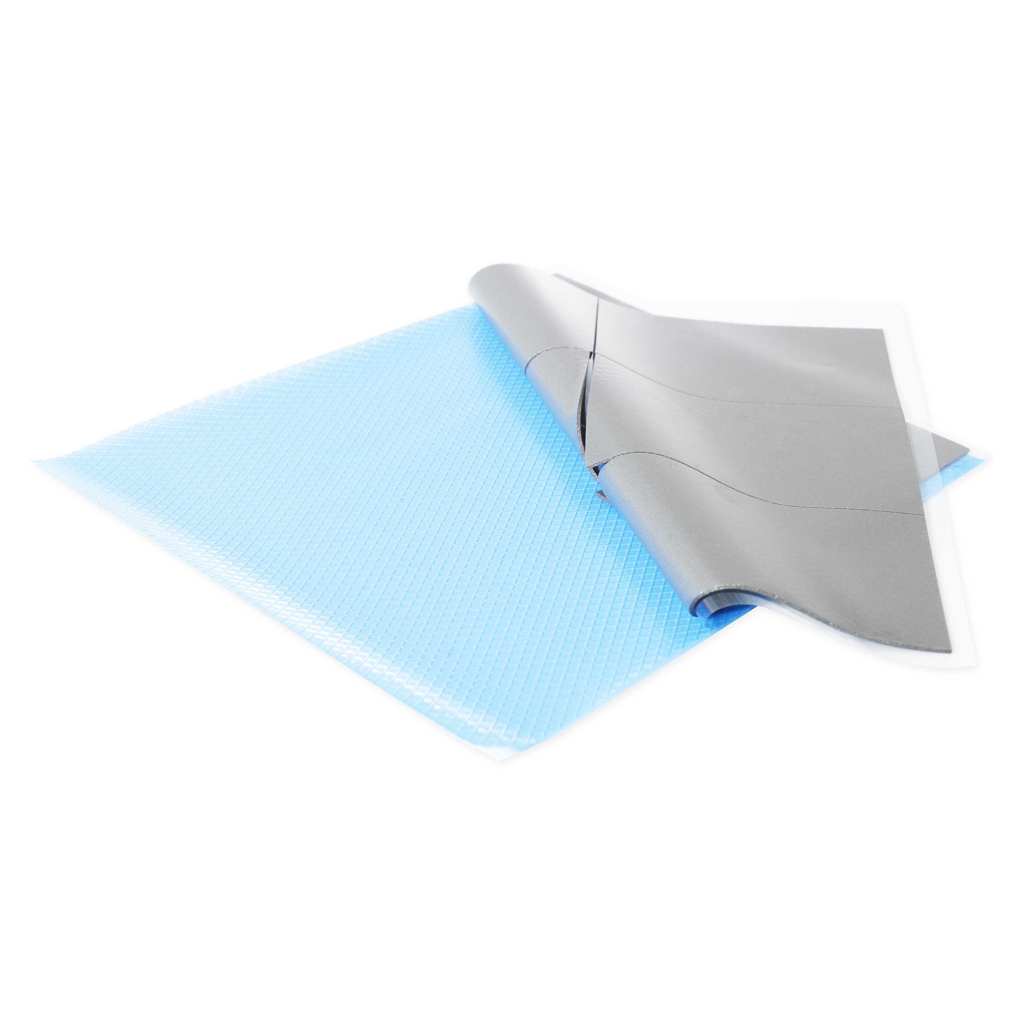
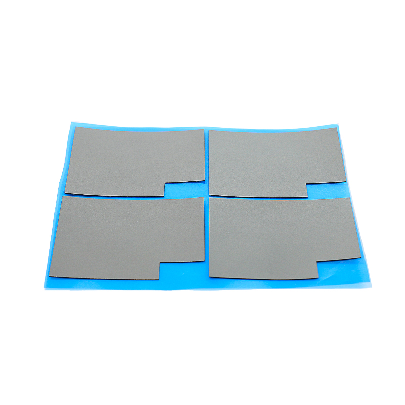
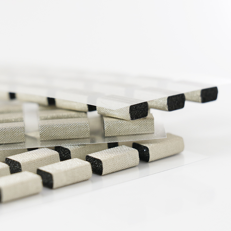
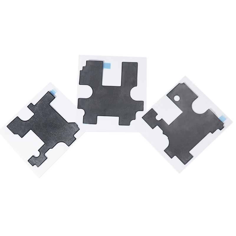
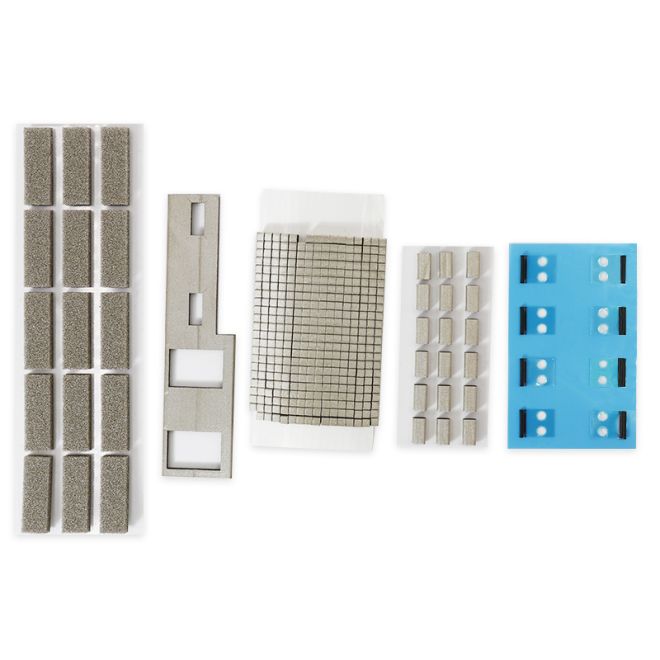
Common forms include strips, gaskets, frames, and die‑cut pads. They match standard housings and custom high‑density boards.
- Profiles for door frames and panel joints
- Custom pads for PCB shielding cans
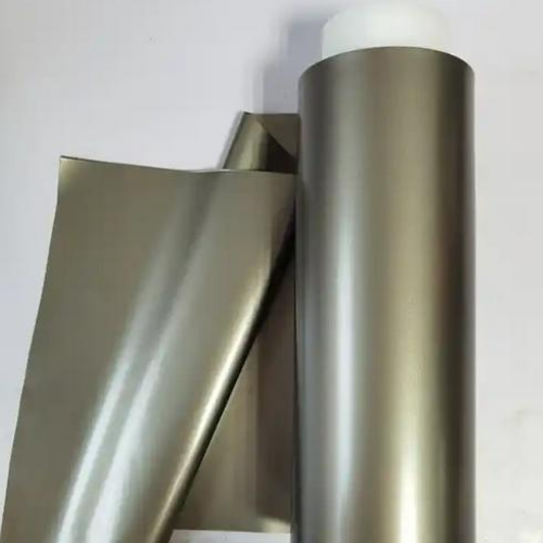
- Rolls for fast mass production
4. Surface Fabric and Plating Systems
Conductive fabrics and plated skins lower contact resistance and increase durability. They also improve abrasion and oxidation resistance.
- EMI Conductive Foam-PU Foam for soft, conformal seals
- EMI Conductive Foam-Conductive Fabric for strong surface shielding
🔌 Electrical Conduction Mechanism Inside Conductive Foam Microstructure
Conductive foam works by forming continuous paths between many small contact points. When compressed, metal or carbon networks link and carry current efficiently.
The microstructure controls resistance, frequency response, and stability. Good design keeps low impedance over changing loads and repeated compression cycles.
1. Percolation Network Formation
Inside the foam, conductive particles or plated cell walls touch and build a 3D network. Once percolation starts, resistance drops quickly.
- Below threshold: few paths, high resistance
- Above threshold: dense paths, stable conduction
- Network strength defines EMI performance
2. Contact Resistance Under Compression
As pressure rises, more micro‑contacts appear and flatten. This lowers contact resistance and improves shielding at joint interfaces.
| Compression | Typical Contact Resistance Trend |
|---|---|
| 10% | High, unstable |
| 25% | Medium, functional |
| 40% | Low, optimized |
3. Frequency Response and Skin Effect
At high frequencies, current flows near the outer surface. Conductive fabrics and plating boost performance by offering a smooth, continuous skin.
- Low MHz: bulk network is key
- High MHz–GHz: surface quality dominates
- Uniform coating helps keep loss low
4. Example Data: Shielding vs. Compression
Engineers often compare shielding level at different compression states to find the best design window for gaskets and pads.
🛡️ Shielding Effectiveness: Key Parameters Affecting EMI and RFI Performance
Shielding performance depends on material conductivity, thickness, compression, and mounting design. Good balance ensures strong EMI and RFI control at low cost.
Designers tune foam choice and geometry to hit target dB levels across the required frequency band.
1. Material Conductivity and Shielding dB
Higher conductivity usually brings higher shielding dB, especially at lower frequencies. Surface quality and joint design fine‑tune real‑world results.
- Bulk resistivity impacts low‑frequency fields
- Surface resistance guides RF behavior
- Uniform plating limits weak spots
2. Geometry, Gaps, and Compression Range
Foam height, width, and compression window define line pressure and leakage risk. Engineers aim for stable contact with minimal gaps.
| Factor | Impact on Shielding |
|---|---|
| Height | Defines working compression range |
| Width | Controls contact area and force |
| Gap size | Large gaps lower dB fast |
3. Environmental Stability and Corrosion
Humidity, salt, and temperature swings can change resistance. Corrosion‑resistant metals and good plating keep shielding stable over product life.
- Nickel and tin layers fight oxidation
- Stable foam cells resist moisture
- Proper storage extends shelf life
📏 Mechanical Properties, Compression Set, and Long-Term Stability of Conductive Foam
Mechanical strength and compression set control how long foam can hold force and keep contact. Poor mechanics quickly reduce EMI performance.
Designers match foam hardness and density to closure force limits in doors, lids, and small housings.
1. Hardness, Density, and Force Curve
Foam hardness and density define load versus deflection. A smooth force curve protects parts and keeps assembly forces predictable.
| Property | Effect |
|---|---|
| Low hardness | Easy closure, lower force |
| High hardness | Higher load, better seal |
| Density | Impacts durability and feel |
2. Compression Set and Recovery
Compression set shows how much height the foam loses after long compression. Low set means better recovery and stable contact.
- Target low compression set at use level
- Control temperature during testing
- Check height after aging cycles
3. Aging, Fatigue, and Environmental Stress
Heat, UV, and chemicals can harden or crack foam. Reliable EMI foam resists these changes and stays flexible over years of service.
- Thermal aging tests at elevated temperatures
- Repeated compression cycles for fatigue
- Chemical splash and humidity checks
🏭 Application Scenarios and Why Engineers Prefer SpringGrass Conductive Foam
Conductive foam supports high‑speed electronics, telecom gear, and consumer devices needing slim, reliable EMI solutions without rigid metal parts.
SpringGrass products provide stable shielding, easy assembly, and consistent quality, helping teams shorten design cycles and meet tight compliance dates.
1. Consumer Electronics and Smart Devices
Phones, tablets, and wearables use foam gaskets around displays, cameras, and antennas to block noise while keeping designs thin and light.
- Edge gaskets for metal frames
- Shielding pads under covers
- Battery contact cushions
2. Telecom, Data Center, and 5G Systems
Base stations, routers, and servers require strong EMI control across wide bands. Conductive foam simplifies cabinet and module sealing.
| Use Case | Foam Function |
|---|---|
| Rack doors | Perimeter EMI gaskets |
| RF modules | Frame and lid seals |
| Backplanes | Grounding interfaces |
3. Automotive, Medical, and Industrial Equipment
Harsh environments demand stable EMI and strong mechanics. SpringGrass foam supports dashboards, control panels, scanners, and industrial controls.
- Vibration‑friendly sealing
- Compatibility with many housings
- Repeatable performance under stress
Conclusion
Conductive foam joins soft mechanical support with reliable electrical conduction. Its microstructure and surface design control shielding, contact resistance, and durability across real‑world conditions.
By tuning foam type, fillers, geometry, and compression, engineers achieve strong EMI control, long life, and smooth assembly in modern electronic systems.
Frequently Asked Questions about conductive foam
1. What is conductive foam used for?
Conductive foam is used for EMI and RFI shielding, grounding, and cushioning. It seals gaps, stabilizes components, and keeps electrical contact in enclosures.
2. How much should I compress conductive foam?
Designs typically use 20–40% compression. This range offers low contact resistance, good shielding, and acceptable closure forces for most housings.
3. Does conductive foam lose performance over time?
All foams age, but quality materials with low compression set and good plating keep stable shielding performance across many years of service.
4. Can conductive foam replace metal finger stock?
In many cases, yes. Conductive foam offers similar shielding with lower closure forces and better tolerance to gaps and mechanical misalignment.
5. How do I select the right conductive foam?
Define frequency range, target shielding dB, compression limits, and environment. Then match foam type, surface finish, and geometry to those needs.





 Privacy settings