



.png)


.png)



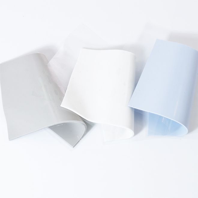
Your PC sounds like a jet engine, your CPU feels like a campfire, and you’re wondering if thermal pads are just expensive stickers. Don’t worry—every builder has asked, “Why is this thing still so hot?”
The fix is choosing the right thermal interface pad, installing it correctly, and checking real performance data. For solid guidance on safe temperatures and testing methods, see this detailed report from Intel on CPU overheating and cooling.
🔥 Understanding Thermal Interface Material Pads: Function, Structure, and Key Roles
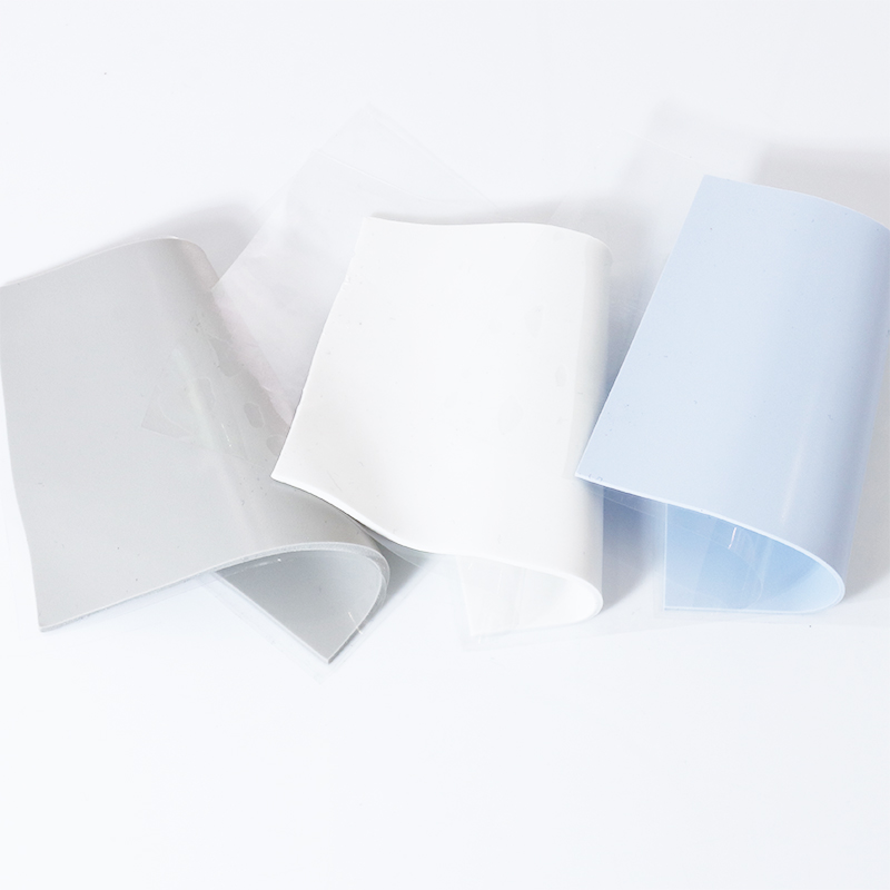
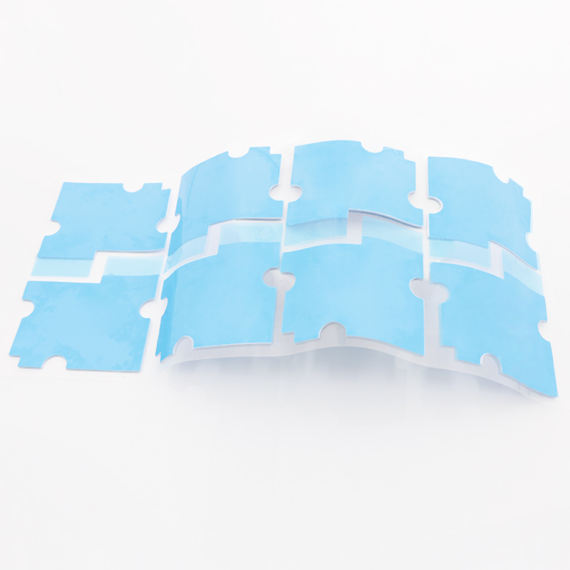
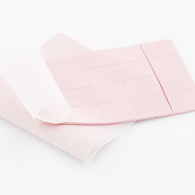
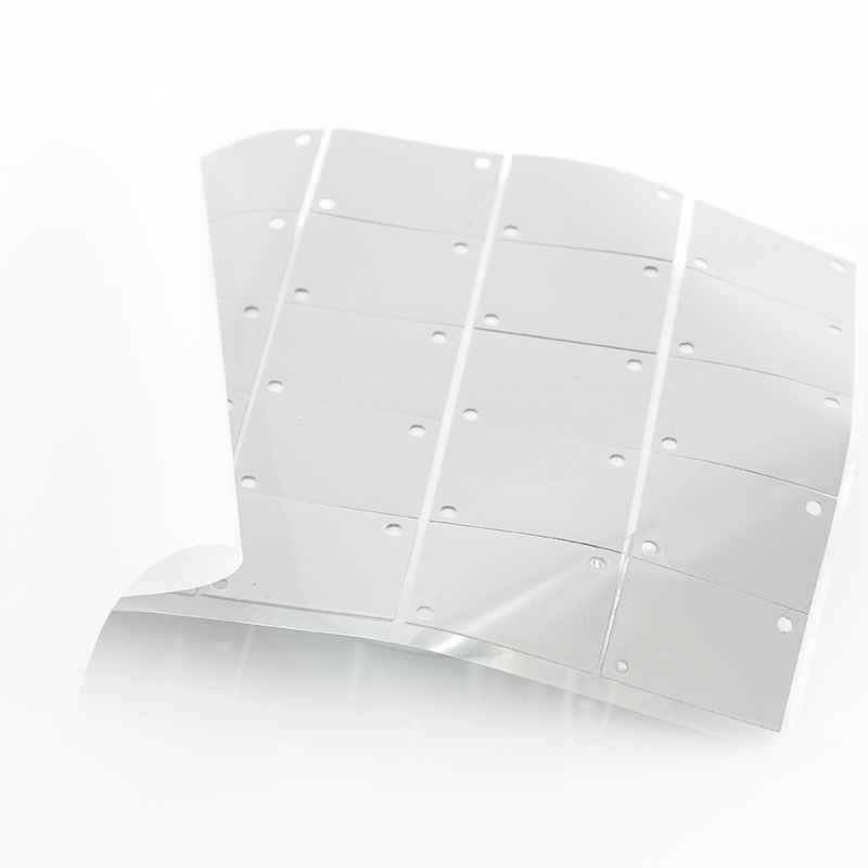
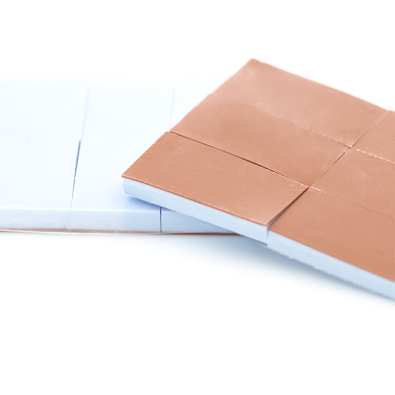
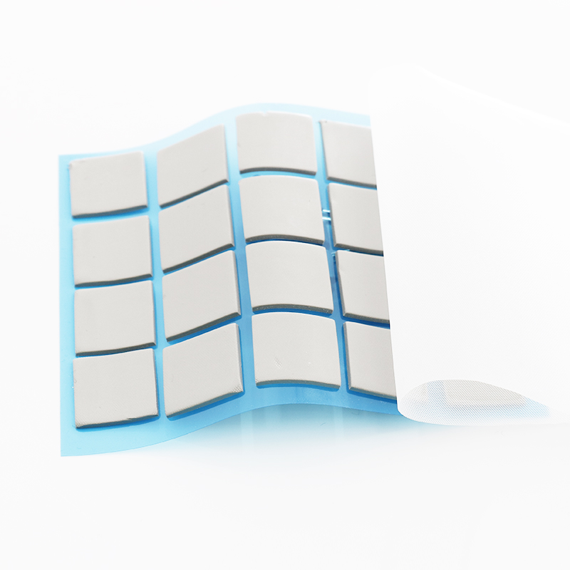
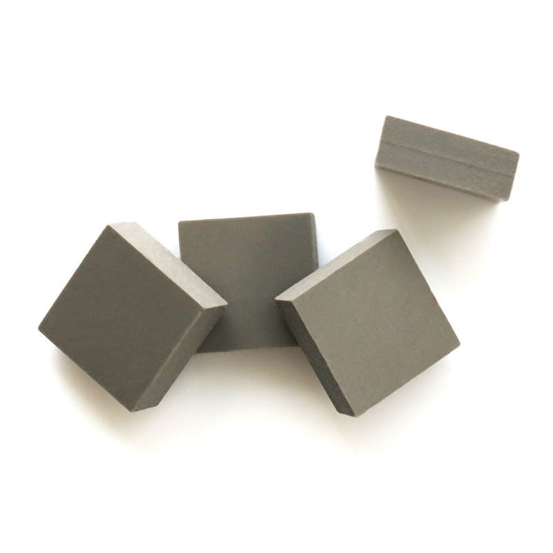
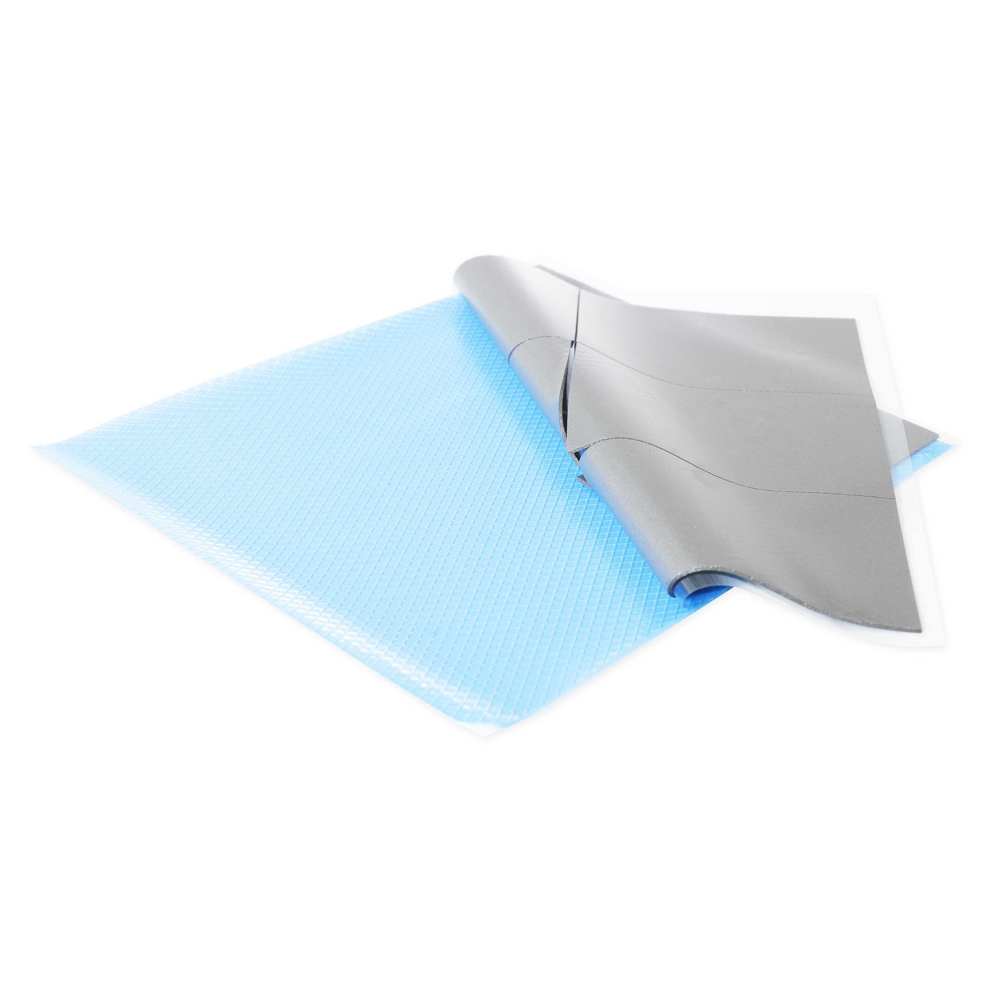
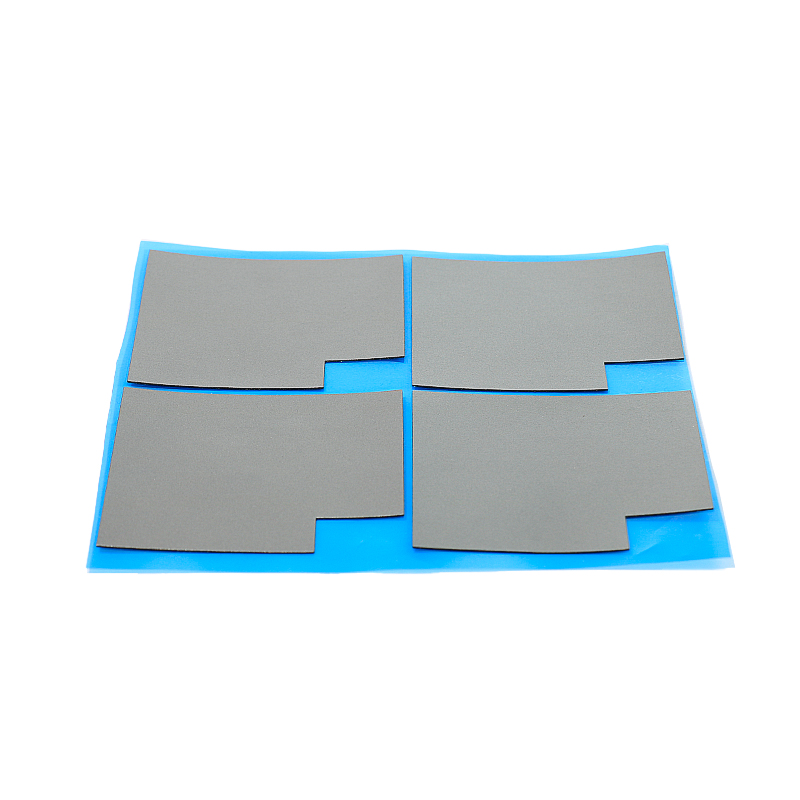
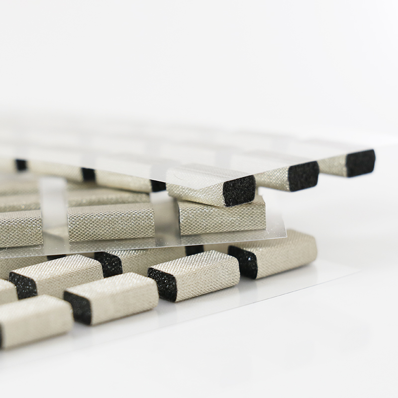
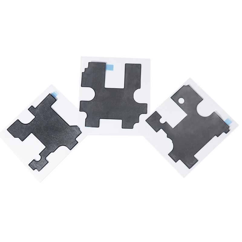
Thermal interface material (TIM) pads fill microscopic air gaps between hot components and heatsinks. They lower contact resistance, improve heat flow, and protect delicate electronic parts.
Well‑designed pads combine softness, strength, and high thermal conductivity. This balance supports stable device temperatures, longer lifetime, and consistent performance under real operating conditions.
1. Basic Working Principle of TIM Pads
TIM pads replace air with thermally conductive material along the contact path. This produces a more even heat spread from chips to heatsinks and metal housings.
- Fill surface gaps and voids
- Increase true contact area
- Reduce interface thermal resistance
2. Internal Material Structure
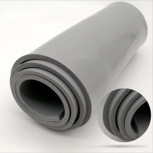
Most pads use a polymer base loaded with ceramic or metal fillers. Filler size and loading strongly affect thermal conductivity and softness.
| Layer | Main Role |
|---|---|
| Polymer matrix | Flexibility and electrical isolation |
| Thermal fillers | Heat transfer path |
| Optional carrier | Dimensional stability |
3. Key Performance Metrics
Engineers compare pads using a few core metrics. These values must match the power level, board layout, and assembly process.
- Thermal conductivity (W/m·K)
- Thickness and compression range
- Hardness and tensile strength
- Electrical insulation and flammability rating
4. Core Roles in Electronic Systems
High‑quality pads not only move heat; they also support mechanical and electrical reliability across many devices and industries.
- Protect chips from stress and vibration
- Support consistent heatsink clamping
- Provide safe isolation between high‑voltage points
🧊 Thermal Conductivity vs. Thickness: Balancing Performance and Mechanical Compliance
Engineers must choose the right combination of pad conductivity and thickness. This balance ensures low thermal resistance while avoiding high stress on components.
Too thin or stiff pads may cause poor contact, while overly thick pads can limit heat flow. Proper design aligns both thermal and mechanical needs.
1. How Conductivity and Thickness Interact
Total thermal resistance depends on both material conductivity and pad thickness. Doubling thickness nearly doubles resistance when conductivity is fixed.
| Pad | Conductivity (W/m·K) | Thickness (mm) |
|---|---|---|
| Low‑power | 1.2 | 1.0 |
| Mid‑power | 3.0 | 0.5 |
| High‑power | 4.0 | 0.5 |
2. Sample Bar Chart: Comparing Pad Options
The bar chart below compares effective thermal performance for common pad grades at equal thickness for quick selection.
3. Mechanical Compliance and Assembly Tolerance
Softer, thicker pads bridge height differences between components. They help avoid bending PCBs and keep clamp forces within safe limits.
- Absorb stack‑up tolerances
- Reduce edge loading on chips
- Support faster assembly alignment
4. Design Tips for Matching Pad Specs
Use low‑k, thicker pads for low heat, and higher‑k, thinner pads for dense, hot areas near power electronics or CPUs.
- Simulate hotspot temperatures early
- Check gap range and flatness
- Validate with real thermal testing
🧱 Compression, Contact Pressure, and Surface Roughness in TIM Pad Efficiency
Compression, clamp pressure, and surface finish work together to define real thermal contact. Good control here can cut interface resistance dramatically.
1. Optimal Compression Range
Each pad has a rated compression window. Staying inside this range gives strong contact without excessive stress on package edges.
| Pad Type | Typical Compression |
|---|---|
| Soft gap pads | 20–40% |
| Reinforced pads | 10–30% |
2. Contact Pressure Management
Too little pressure maintains air pockets; too much can crack components. Use even mounting and calibrated screws for repeatable pressure.
- Use torque‑controlled fasteners
- Apply cross‑pattern tightening
- Check pressure with test shims where needed
3. Surface Roughness and Flatness
Smoother, flatter surfaces need less pad thickness and reach lower thermal resistance. Simple machining changes often bring big gains.
- Use milled or ground heatsink bases
- Remove burrs and bowing
- Clean surfaces before assembly
📊 Reliability Factors: Aging, Pump-Out, and Long-Term Thermal Stability
Thermal pads must keep performance over years. Aging, pump‑out, and material changes under heat can raise interface resistance slowly.
1. Aging Under Heat and Humidity
Long exposure to high temperature and moisture can harden pads. This reduces compliance and increases contact resistance over time.
- Test with powered life and HALT
- Review high‑temperature storage data
- Watch for cracking or shrinkage
2. Pump-Out and Mechanical Cycling
Repeated thermal cycling can move material away from the hotspot zone. Stable formulations resist flow and keep coverage intact.
| Risk Factor | Mitigation |
|---|---|
| Large CTE mismatch | Use softer pads |
| High vibration | Choose reinforced types |
3. Monitoring Long-Term Thermal Stability
Measure device case and heatsink temperatures over life tests. Stable pads show little drift from initial thermal performance.
- Log hotspot temperatures
- Compare before/after interface checks
- Correlate with field failure data
🌱 Selecting the Right Pad for Your Application: Choose SpringGrass Solutions
Choosing the correct pad means matching power level, gap size, and mechanical limits. SpringGrass offers tuned solutions for different thermal and assembly needs.
1. For General Electronics and Moderate Power
The 1.2W/mk Thermal Pad HRTP-M16-T01250NN Series fits low‑to‑mid power modules where cost, softness, and reliable insulation matter most.
2. For High Power Density and Tight Gaps
The 4W/mk Thermal Pad HRTP-M16-T040 Series targets power supplies, inverters, and LED drivers that demand strong heat transfer in compact designs.
3. For Added Mechanical Support and Handling
The 3W/mk Thermal Pad with PI Film HRTP-M16-T03060PN Series includes PI film reinforcement, ideal when you need clean handling and higher tear resistance.
Conclusion
Well‑selected thermal interface pads unlock stable, cool, and reliable electronics. Focus on conductivity, thickness, compression, and surface finish to lower interface resistance.
By matching SpringGrass pad families to your thermal and mechanical targets, you gain predictable performance and smooth assembly across prototypes and mass production.
Frequently Asked Questions about thermal interface material pad
1. How do I choose the right thermal pad thickness?
Measure the real gap between components and heatsink at all corners, then select a pad whose compressed thickness safely covers the largest measured gap.
2. Are thermal pads reusable after disassembly?
Often no. Once compressed, pads may tear or lose shape when removed. For reliable performance, replace pads whenever you reopen a thermal joint.
3. Do pads conduct electricity?
Most TIM pads are electrically insulating while conducting heat. Always check dielectric strength and insulation ratings in the datasheet before use in high‑voltage areas.
4. When should I choose pads instead of thermal grease?
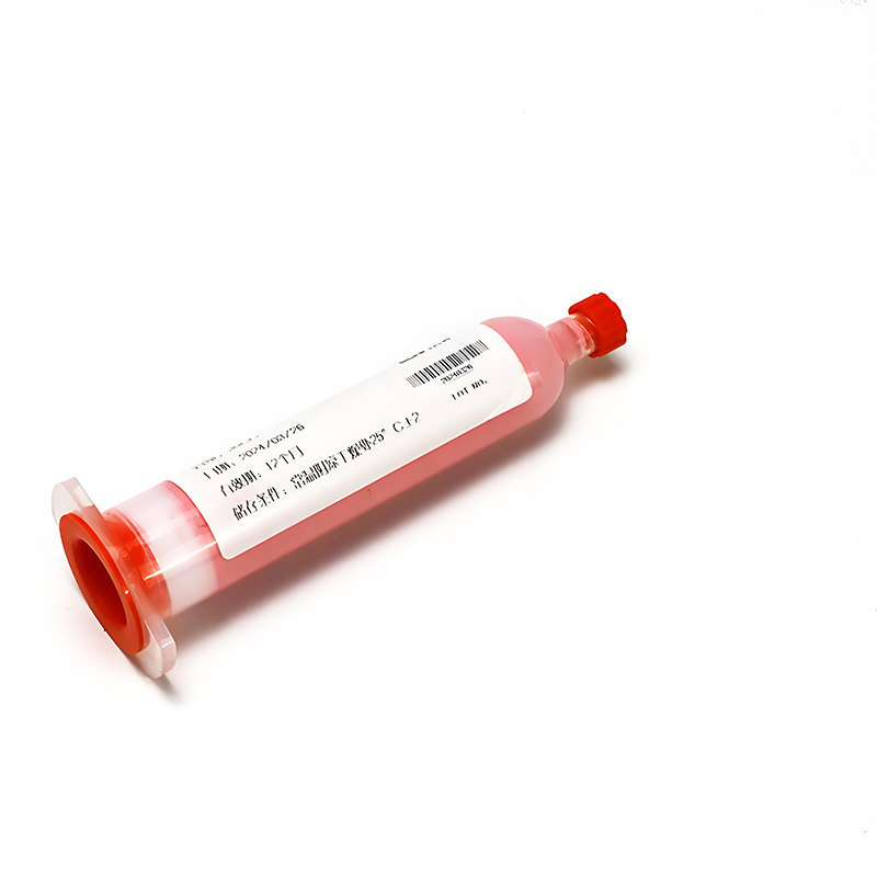
Use pads when you need clean assembly, consistent thickness control, electrical isolation, or when large gaps and tolerance stacks must be filled.





 Privacy settings